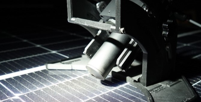
ILMD with conoscope measuring a solar panel
Reflection measurement of solar panels
High-resolution measurement of the angular luminance reflection and reflectance of photovoltaic modules using the LMK luminance camera
Application Note – Reflection measurement of solar panels using ILMDs
This page shows a summary of the application note. Topic of the document is Workflow for the efficient measurement of reflection properties using imaging luminance measurement cameras, using the example of a solar panel
Issue
Indoors and outdoors, many different surfaces and materials have a wide range of reflective properties. These can be actively used in architecture and lighting design. However, there are also undesired effects, such as glare from highly reflective surfaces. Solar panels on roofs or facades, which must be exposed to direct sunlight at various angles, may cause such glare. In the city of Vienna, for example, an expert must rule out a possible impairment due to glare under certain circumstances to obtain a permit to construct a PV system (Guideline MA 37 – 476239-2022 point 6.2). This problem quickly becomes very complex due to the wide range of different solar cells, which have different reflection mechanisms and properties.
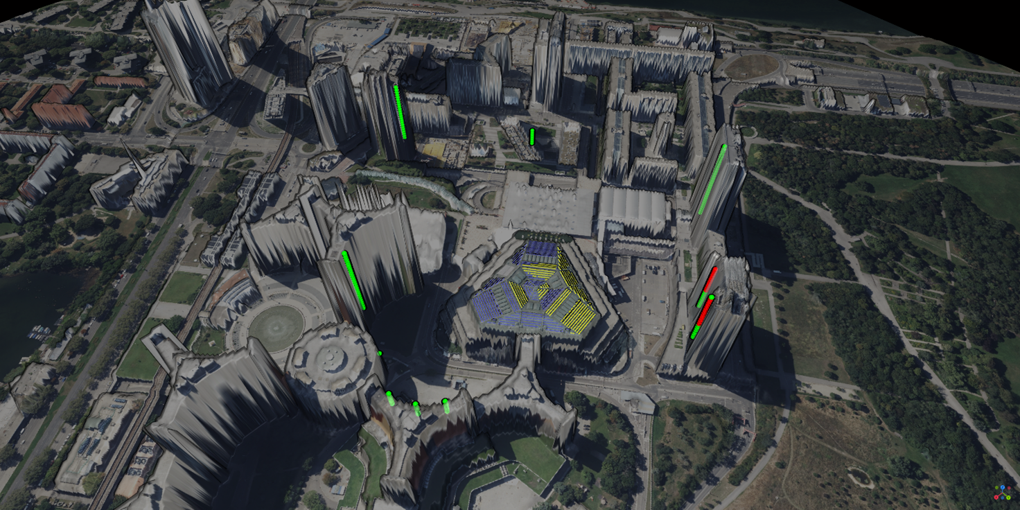
Figure 1: Various glare evaluations in a real solar-panel installation
Figure 1 shows an example of a real glare situation. In this installation, conventional solar panels are colored blue and reflection-optimized solar panels yellow. The green-colored areas show immission points where the cumulative glare duration complied with the limit of 30 h/year. This limit was exceeded for the red immission points.
Aim
The required data for the analysis must be measured in advance under reproducible conditions in a dark laboratory for the corresponding solar panel(s). One possibility is to use a multi-axis goniometer to scan the complete bidirectional reflectance distribution function (BRDF) using a light source and a spot meter. Specialized systems are available for this purpose. However, these systems are very expensive and the measurements are time-consuming and complex. This article presents a significantly more flexible and cost-effective method of measuring reflection properties using an imaging luminance measurement device.
Description of the innovation/best practice
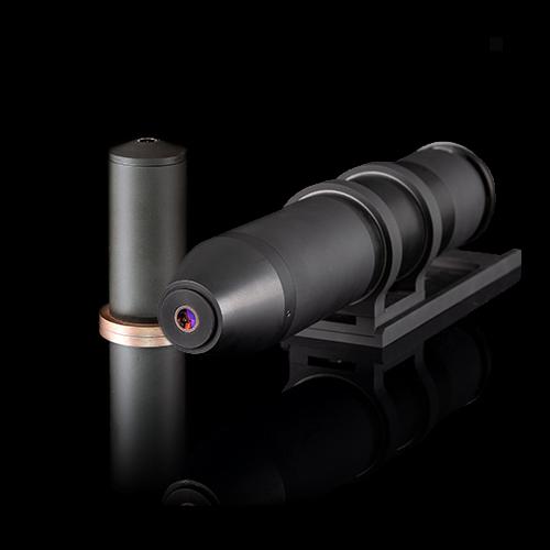
For the reproducible measurement of such reflections, a luminance camera with type-II calibration (ILMD Type II) is used. The measurement principle is shown in Figure 2. The required setup is simple and flexible, thanks to an automatic geometric alignment algorithm that can be easily implemented with a printed alignment image. This makes the approach well-suited for situations where it is necessary to frequently switch between different types of measurement tasks. One example of this would be to measure vastly different angles of incidence. In addition, light source properties are easily corrected using appropriate correction measurements. This way, comprehensive data can be collected quickly. The resulting information can then be used for further verification.
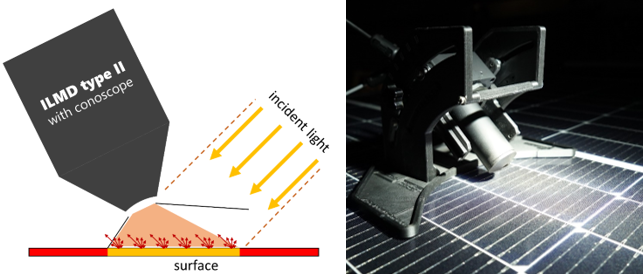
Figure 2: Principle of conoscopic reflection measurement (left) and example setup based on a solar panel measurement (right)
Level of realization
The presented workflow with commercially available hardware and software was used to measure different solar panels (conventional and reflection-optimized). Exemplary measurements on two solar panels are shown for two angles of incidence in Figure 3. Each false-color image shows the measured reflection coefficient q for different viewing angles in the solar panel coordinate system on a logarithmic scale. In addition, the method was validated in a round-robin measurement.
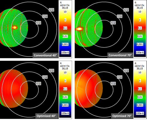
Figure 3: Angle-dependent reflection coefficient for two angles of incidence for two solar panels