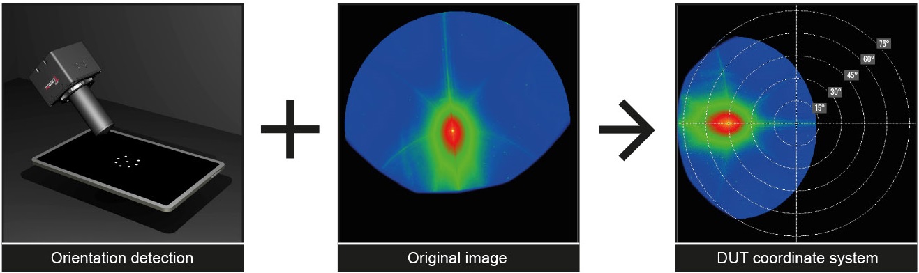
Example of orientation detection using a display setup
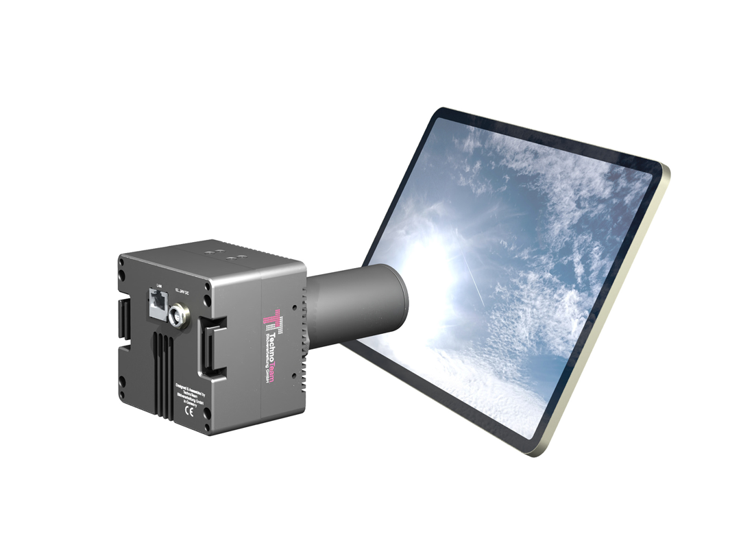
LMK Reflection: Imaging, Angle-Resolved Display Reflectance
High-resolution reflectance measurement with luminance camera
Our luminance measurement camera (LMK)-based reflectance measurement enables fast and high-resolution evaluation of reflectance properties and is part of the Display Package. In contrast to conventional, goniometer-based methods, the system captures detailed luminance and color information in a single measurement setup - with minimal effort. LMK Reflection thus replaces conventional spot meter methods with a high-resolution imaging solution that efficiently captures reflection properties with angular resolution.
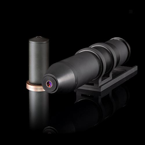
The use of a type II calibrated LMK with a conoscopic lens ensures that both the measurement sample and the light source are in focus. Automatic orientation detection minimizes positioning effort and enables a fast, robust setup. Measurement results are automatically transformed into the coordinate system of the measurement sample - for intuitive and standard-compliant evaluation.
Key Benefits at a Glance
- Maximum Flexibility and Ease of Use
- No goniometer, no motorized axes: Fast and simple setup
- Quick alignment via orientation detection
- Versatile use and evaluation: Ideal for R&D, compliance testing, and comparative measurements
- Comprehensive Measurement in a Single Setup
- Wide angular range: Capture multiple viewing directions in a single image
- Live transformation into the DUT's spherical coordinate system
- Simultaneous sharp focus on both DUT and light source
- Accurate and Robust Results
- High measurement stability through type II calibration and orientation detection
- Indirect illuminance measurement
- Optimized for complex reflection distributions and diffractive effects
Upgrade Your Reflection Measurements
LMK Reflection offers a powerful, flexible, and high-resolution solution for modern reflection analysis.
Contact our experts today to discuss your application or request a demo!
Case Study: ISO 15008-Compliant Reflection Measurement
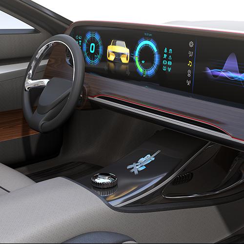
Our solution enables reliable compliance testing according to ISO 15008 (external link). The standardized measurement geometries (e.g. CID 45°/20° or IC 25°/0°) can be set up quickly and without mechanical complexity.
The high-resolution capture of reflections across multiple viewing directions allows for precise evaluation within the driver’s field of view in a single setup. By using a flexible region-of-interest (ROI) definition, local effects such as diffraction patterns can also be analyzed in detail.
Measurement data is automatically scaled to a target illuminance of 45 klx and transformed into the spherical coordinate system of the DUT, ensuring straightforward and standard-compliant evaluation.
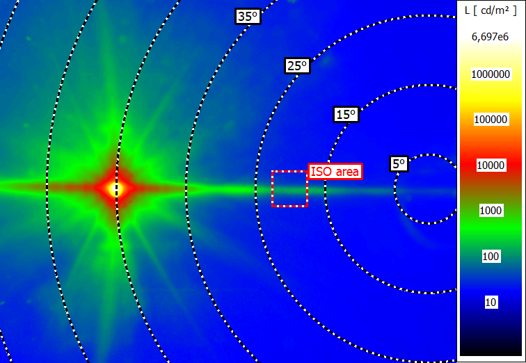
Measurement image for an in-plane CID evaluation (45°/20°)
Case Study: Separation of Reflectance Components
When combined with a variable-aperture annulus light source, our imaging-based system enables precise separation of Lambertian and specular reflectance—all in a single setup.
This approach allows for detailed evaluation of haze and diffractive structures, which are increasingly relevant for modern display surfaces. By capturing many viewing directions simultaneously, even subtle reflection characteristics become visible and quantifiable.
The measurement process supports evaluations according to key international standards such as ISO 9241-307, IEC 62977-2-2, and IDMS (external links) 1.3 chapter 11.7.3
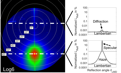
Visualization of display reflection components in a single image
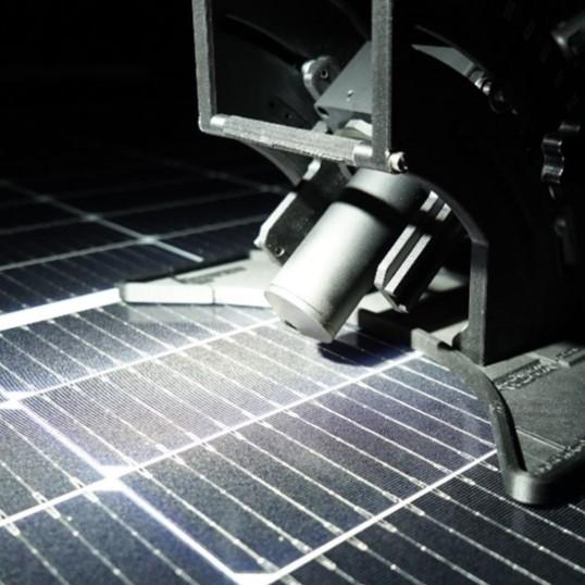
Case Study: Glare Evaluation for Photovoltaic Panels
Our LMK Type II-based system has also been successfully applied in glare assessments for photovoltaic installations, such as those required by urban guidelines in Vienna (e.g., MA 37 – 476239-2022).
Compared to multi-axis goniometric BRDF measurements, our solution offers a faster and more flexible workflow. The automatic geometric alignment via printed test patterns ensures a reproducible setup, even when switching between panel types or incidence angles.
The high-resolution measurement images allow for detailed reflection analysis under standardized conditions. Results can be used to verify compliance with glare limits (e.g. <30 hours/year at specific immission points), and to compare conventional vs. reflection-optimized solar panels.
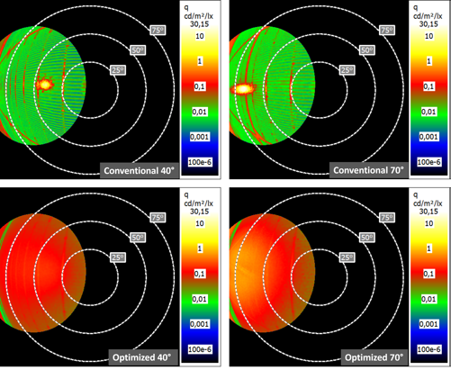
Example measurement images of the reflectance of two solar panels at angles to the sun of 40° and 70°
FAQ — LMK Reflection
What is LMK Reflection and what does the add-on do?
LMK Reflection captures the full angular reflectance distribution of a display in a single image — replacing complex spot meter and goniometer setups with one fast, standard-compliant measurement. Technically, the LabSoft add-on pairs a type II-calibrated LMK luminance camera with a conoscopic lens, an automatic orientation-detection algorithm, and geometric processing into the device-under-test (DUT) coordinate system.
How does LMK Reflection differ from spot meter and goniometer methods?
A conventional spot meter delivers a single integrated value for the aligned viewing direction. Goniometric scanning can produce many such values by moving the spot meter through different orientations — but each reading requires its own movement and acquisition step, so a full scan typically takes minutes to hours. In addition, every individual reading is still integrated over the spot meter's measurement field (the angular cone over which the device averages), so even at very fine scan resolution this measurement field smooths out steep reflection peaks and limits the angular detail that can ultimately be resolved.
An imaging ILMD type II instead captures all relevant viewing directions in a single exposure (seconds), and maps each sensor pixel to a much smaller angular cone — so the angular resolution is set by the camera's optical resolution and pixel size rather than by an integrated measurement spot. The result: comprehensive angular data acquired at once, finer angular detail preserved — and because the full angular distribution is visible in every shot, the operator can see directly where alignment is critical (regions with steep luminance gradients) and where it is uncritical. With a single spot meter reading this information is hidden by definition: a steep-gradient zone looks the same as a flat one, and you may be sitting on a misaligned peak without ever noticing.
Which standards does LMK Reflection support?
The relevant display-reflection standards (ISO 15008, IEC 62977-2-2, IDMS 1.3, ISO 9241-307) were originally written assuming spot meter measurements. The imaging approach is fully consistent with their definitions and limit values — the same quantities (specular, haze, Lambertian reflectance) are evaluated, but with much richer angular data and lower setup complexity. In particular:
- ISO 15008 – legibility of in-vehicle visual displays under ambient light (minimum 2:1 contrast, geometries CID 45°/20° and IC 25°/0°, 45 klx target illuminance).
- IEC 62977-2-2 – reflectance measurements on electronic display modules.
- IDMS 1.3 chapter 11.7.3 – International Display Metrology Standard (SID/ICDM).
- ISO 9241-307 – ergonomic requirements for electronic visual displays.
What is "type II calibration" and why is it essential for reflectance measurements?
A type II ILMD is calibrated photometrically (V(λ)-matched) and geometrically: every sensor pixel maps to a defined direction in space. The camera therefore delivers luminance as a function of viewing angle directly — the prerequisite for compliant CID/IC evaluation and for separating reflection contributions across the full angular distribution. Type II calibration is also available for color-capable LMK variants, so reflected color can be evaluated within the same workflow when needed.
What is the orientation-detection algorithm and how much setup time does it save?
Instead of mechanically aligning the display to the camera (mandatory with goniometer or spot meter setups), a printed or displayed test pattern is shown on the DUT. An algorithm reconstructs the geometric pose of the DUT relative to the camera and transforms each captured image live into the DUT's spherical coordinate system. This procedure minimizes alignment effort, makes switching between measurement geometries (e.g. CID ↔ IC) straightforward, and is particularly valuable for prototypes or for DUTs that lack standardized mounting fixtures — typical situations in early-stage and automotive development.
How well do LMK Reflection results compare to classical spot meter and goniometer measurements?
The imaging method has been cross-validated against classical reference setups. The LMK-based workflow was compared to 16 conventional spot meter / goniometric reference measurements for both the specular and the Lambertian reflectance components. The imaging results agree with the conventional references within typical measurement uncertainty. The imaging-based approach therefore delivers values that are quantitatively equivalent to the established reference methods — while at the same time providing the additional angular detail that spot meter integration cannot resolve.
The full study is available open-access via TU Darmstadt.
Which reflection components can be evaluated from the captured data?
LMK Reflection itself captures the full angular reflection distribution in a single image. The classical components — specular, haze, and Lambertian — are then evaluated in post-processing of this data, for example with the annulus-source method demonstrated in our J-SID case study, which uses a variable-aperture source to isolate the contributions:
- Specular component — mirror-like reflection of the light source; depends on its luminance.
- Haze component — near-specular scattering around the gloss angle; depends on illuminance and on the angular subtense of the source.
- Lambertian component — diffuse, isotropic component; depends on illuminance only.
The high-resolution imaging data also makes a diffractive contribution accessible for analysis.
What is the diffractive reflection component and why should it be measured?
The pixel and sub-pixel arrangement of a display acts as a periodic micro-structure. When ambient light hits this structure, it is diffracted into discrete orders — visible as a colorful, rainbow-like pattern of bright spots outside the specular direction (most easily observed on some OLED phones under direct sunlight). This is the diffractive reflection component. Measurements with a variable-aperture source show that it scales linearly with the source luminance and depends on the angular subtense of the source — making it especially relevant for small, bright sources (the sun!) and therefore for legibility in sunlight. With an ILMD type II + conoscope, the diffractive component is captured spatially and angularly resolved in a single shot — something hardly accessible through spot meter integration.
How does LMK Reflection support ISO 15008 conformity testing for automotive displays?
ISO 15008 mandates a minimum 2:1 contrast for driver-relevant displays under direct sunlight (45 klx, CID 45°/20° or IC 25°/0°). LMK Reflection meets the requirement with a much faster setup than the spot meter reference method: setup without a goniometer, automatic transformation into the DUT coordinate system, and ROI-based evaluation in the driver's field of view. The method has been validated in a round-robin study with five vehicle displays across multiple labs.
Which LMK cameras are compatible?
LMK Reflection is available for the LMK 6 series (LMK 6-5, 6-12, 6-30) in combination with the Conoscope Compact lens.
- Monochrome variants are recommended for standards-compliant V(λ)-luminance measurements.
- Color (filter-wheel) variants additionally enable evaluation of reflected color — relevant for premium display interiors and diffractive effects.
Existing LMK 6 systems can be upgraded; please contact us for retrofit advice.
Can LMK Reflection be used outside the display domain?
Yes. A typical example is glare assessment for photovoltaic installations (e.g. the Vienna guideline MA 37 – 476239-2022, which limits cumulative glare to < 30 h/year at defined immission points). Instead of full-angular BRDF scans on multi-axis goniometers, an imaging setup suffices — including automatic alignment via test patterns and fast switching between angles of incidence. The angle-resolved false-color images allow objective comparison of conventional and reflection-optimized PV modules.
Do I need a separate illuminance meter for the reflection measurements?
No. The light source is characterized with the same LMK camera against a Lambertian reflectance standard. From this data, the illuminance at the DUT surface is derived — a separate illuminance meter is not strictly required.
How reproducible are the results across laboratories?
The method has been validated in a round-robin study with five vehicle displays and multiple participating labs; each lab used a different LMK that received the same type II calibration. Reproducibility relies on factory calibration, the algorithm-based orientation detection, and a documented workflow.
The full workflow article is available open-access as "Optimized Workflow for Fast and Precise ISO 15008 Contrast Evaluation Under Ambient Light" in Information Display Magazine.
Can sparkle, MTF, and reflection be measured on the same platform?
One V(λ)-matched LMK type II covers four standards relevant for cover-material — sparkle, MTF, reflection, and ambient-contrast — by swapping lenses and configuring the geometry:
- IEC 62977-3-9 – Sparkle (standard lens)
- IEC 62977-3-6 – MTF / resolution capability (macroscopic lens)
- IEC 62977-2-1 – Reflection (conoscope lens)
- ISO 15008 – Contrast under ambient light (conoscope lens)
One platform therefore replaces several dedicated instruments for the full characterization of display cover materials (anti-glare layers, AR coatings, structured glass).
RELEVANT PRODUCTS AND APPLICATIONS

Publications
High-resolution reflection measurements made easy, using the example of vehicle displays
16. International Symposium on Automotive Lighting
Understanding the reflective properties of materials is essential for optimizing their appearance under ambient lighting conditions. In the case of automotive interiors, this applies particularly to directional sunlight. However, conventional measurement setups are often complex or provide only limited information. We present a novel solution for fast, high-resolution reflectance measurements that combines high flexibility with a simple setup. This approach uses an imaging luminance measurement device (ILMD) with a special lens and type II calibration. This means that the ILMD is both photometrically and geometrically calibrated. This way, we know the exact sensor pixels of each captured light ray and can assign an angular coordinate. Instead of fixed, pre-defined geometric positioning, we use a test pattern and a specific algorithm to calibrate the alignment of the lens relative to the measurement surface. This allows for flexible setups, and any captured image can be directly converted into the angular coordinate system of the surface under test. Using the luminance camera and a Lambertian reflectance standard, the light source can be set up and calibrated regarding direction, illuminance, angular subtense and uniformity. We verify the method by comparing it to 16 conventional measurements for the specular and Lambertian reflectance. Finally, we validate the concept in a case study in which we quantify the reflective properties of five different vehicle displays to evaluate readability in sunlight according to ISO 15008 in a round-robin test involving multiple laboratories, each using different ILMDs that received the same type II calibration.
Distinguished Paper: Measuring and Characterizing the Diffractive Component in Display Reflection
SID 2025
The authors present and validate an easy-to-set up approach to measure the reflection properties of a display that can measure not only the specular, haze, and Lambertian components of display reflection, but also the diffractive component. They then research the fundamental dependencies of this fourth reflection component through a series of measurements using a variable aperture source.
Measuring and characterizing the diffractive component in display reflection
Society for Information Display 2025
We present and validate an easy-to-setup approach to measure the reflection properties of displays. It is based on a wide field of view conoscopic lens in conjunction with an orientation detection algorithm. Using this approach, we can measure not only the specular, haze, and Lambertian components of display reflection but also the diffractive component. We then investigate the fundamental dependencies of this fourth reflection component through a series of measurements using a variable aperture source and an LC and OLED display. Through these experiments, we can show that the diffractive component scales linearly with the light source's luminance and depends on the angular subtense of the light source.
Optimized Workflow for Fast and Precise ISO 15008 Contrast Evaluation Under Ambient Light
Information Display 2025
The imaging luminance measurement device type II-based method is a promising way to verify the conformity of the legibility of automotive displays.
- Type:
- Add-On
- Applications:
- Architecture Automotive Aviation Display Infrastructure
- Measurands:
- Color measurement Light measurement
- Tasks:
- Development & Industry Science & Research