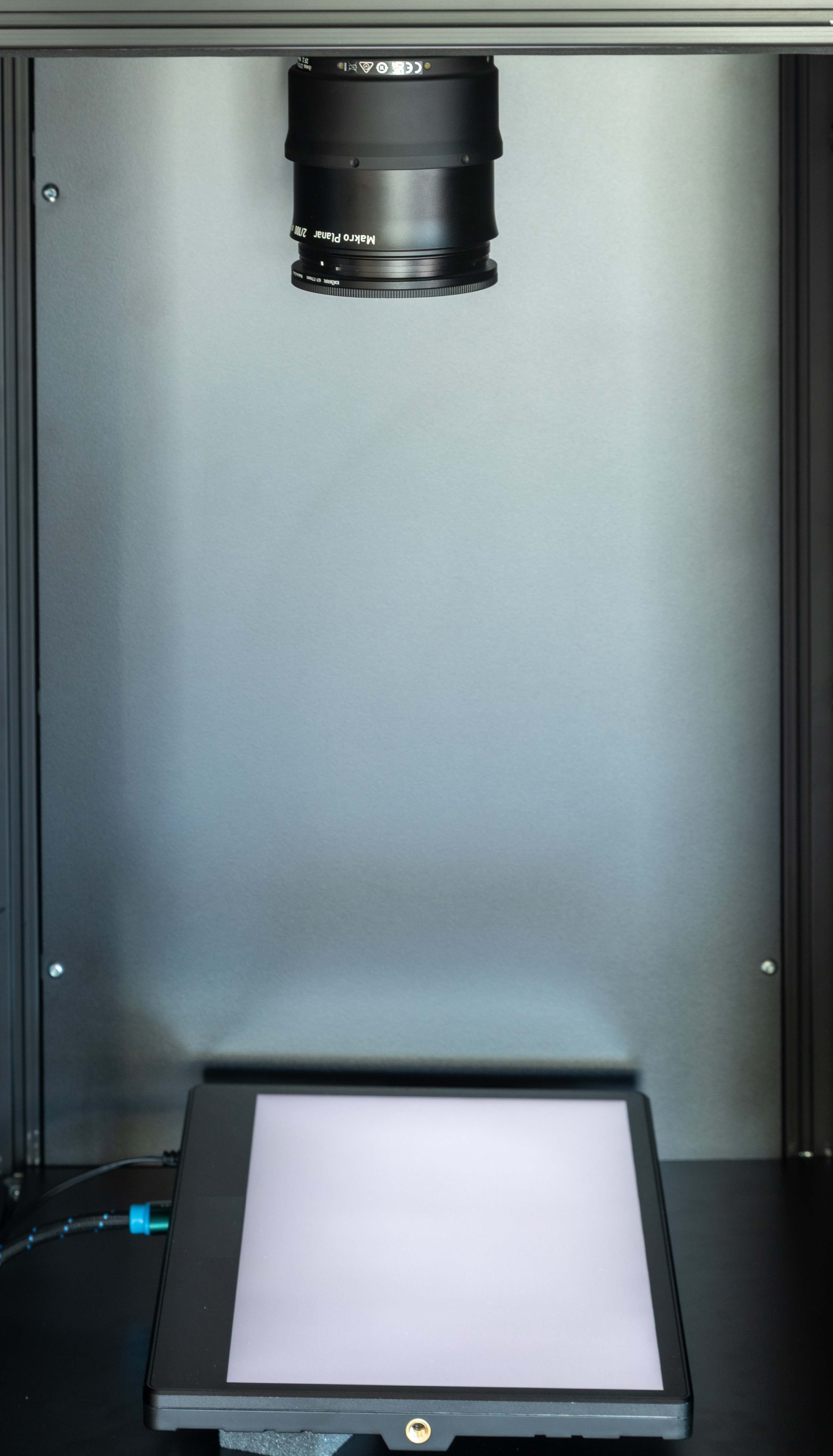
LMK during DeMura measurement
DeMura & Pixel-Level Measurement
With the LMK 7 camera and LMK DeMURA software, TechnoTeam introduces a new measurement approach to DeMura correction on today's fine-pitch OLED, µLED and LED displays. It combines APR for sub-pixel emitter registration, SPR for production-speed capture, and the patented µShaking method for Moiré suppression at sampling ratios optimized for production.
The workflow covers flat and slightly curved emitter surfaces alike — from OLED smartphone panels to curved automotive cluster and center information displays (CID) — because APR teaches the imaging geometry of the actual DUT, not an idealised flat one.
At a glance
- APR — pure software; sub-pixel emitter registration on the sensor
- SPR — production-speed variant of APR; one luminance image per test input signal after teaching
- µShaking — optional on the LMK 7; TechnoTeam's patented method (US 12,387,297 B2) for Moiré suppression at low sampling ratios
What is APR?
Advanced Pixel Registration (APR) is TechnoTeam's software workflow for pixel-level luminance measurement. A dense geometric registration pattern (point cloud), delivered as a dedicated test image, teaches the exact sub-pixel position of every emitter on the sensor — automatically, without manual alignment. That sub-pixel knowledge is what enables pixel-level luminance measurement at low sampling ratios, without having to match the camera grid to the display grid by optics alone.
APR is pure software: independent of geometric LMK calibration, and technically independent of µShaking. Where the native sampling ratio allows, APR alone is enough; denser panels and tighter working distances benefit from the optional µShaking stage.
Single Shot Pixel Registration (SPR) — the production-speed variant
On a production line the same display type is measured thousands of times, ILMD imaging conditions are stable, and each new DUT only shifts or rotates slightly. Single Shot Pixel Registration (SPR) exploits this stability: after a one-time teaching phase on the first panel of a batch, each subsequent DUT is registered and measured with one image capture per test input signal — the registration pattern is not re-taught for every panel.
Validation against full APR shows Q ≥ 0.98 correlation between the SPR luminance map and the full-APR map, measured across shift, rotation and combined misalignments typical for a production control environment. SPR loses no luminance accuracy while saving the registration capture on every DUT.
Throughput: APR vs. segmented capture
Per DUT, APR needs one registration image (three for RGB panels — one per colour channel) plus one luminance image per test input signal. Segmented capture, by contrast, needs n² images per test input signal (where n is the row/column stride). After teaching, SPR drops the per-DUT cost to one luminance image per test input signal.
| DeMura test case | APR | SPR | Segmented capture (n=2) | (n=3) | (n=4) |
|---|---|---|---|---|---|
| Monochromatic, 1 test pattern | 2 | 1 | 4 | 9 | 16 |
| Monochromatic, 3 test patterns | 4 | 3 | 12 | 27 | 48 |
| RGB, 1 test pattern each | 6 | 3 | 12 | 27 | 48 |
| RGB, 3 test patterns each | 12 | 9 | 36 | 81 | 144 |
| DeMura test case | SPR | Segmented capture (n=2) |
|---|---|---|
| Monochromatic, 1 test pattern | 1 | 4 |
| Monochromatic, 3 test patterns | 3 | 12 |
| RGB, 1 test pattern each | 3 | 12 |
| RGB, 3 test patterns each | 9 | 36 |
APR + µShaking — Moiré-proof accuracy at low sampling ratios
When the emitter grid and the sensor grid interact at unfavourable sampling ratios, Moiré artefacts become the dominant error source. The prior state of the art suppresses Moiré either by increasing the sampling ratio (high-magnification optics, larger working distance) or by defocusing — both come at a cost: larger setups, slower cycle times, or loss of sub-pixel resolution.
The optional µShaking sensor stage on the LMK 7 — also known as Phase Compensation DeMoiré — decouples the emitter and sensor grids between captures, suppressing both high- and low-frequency Moiré without losing resolution.
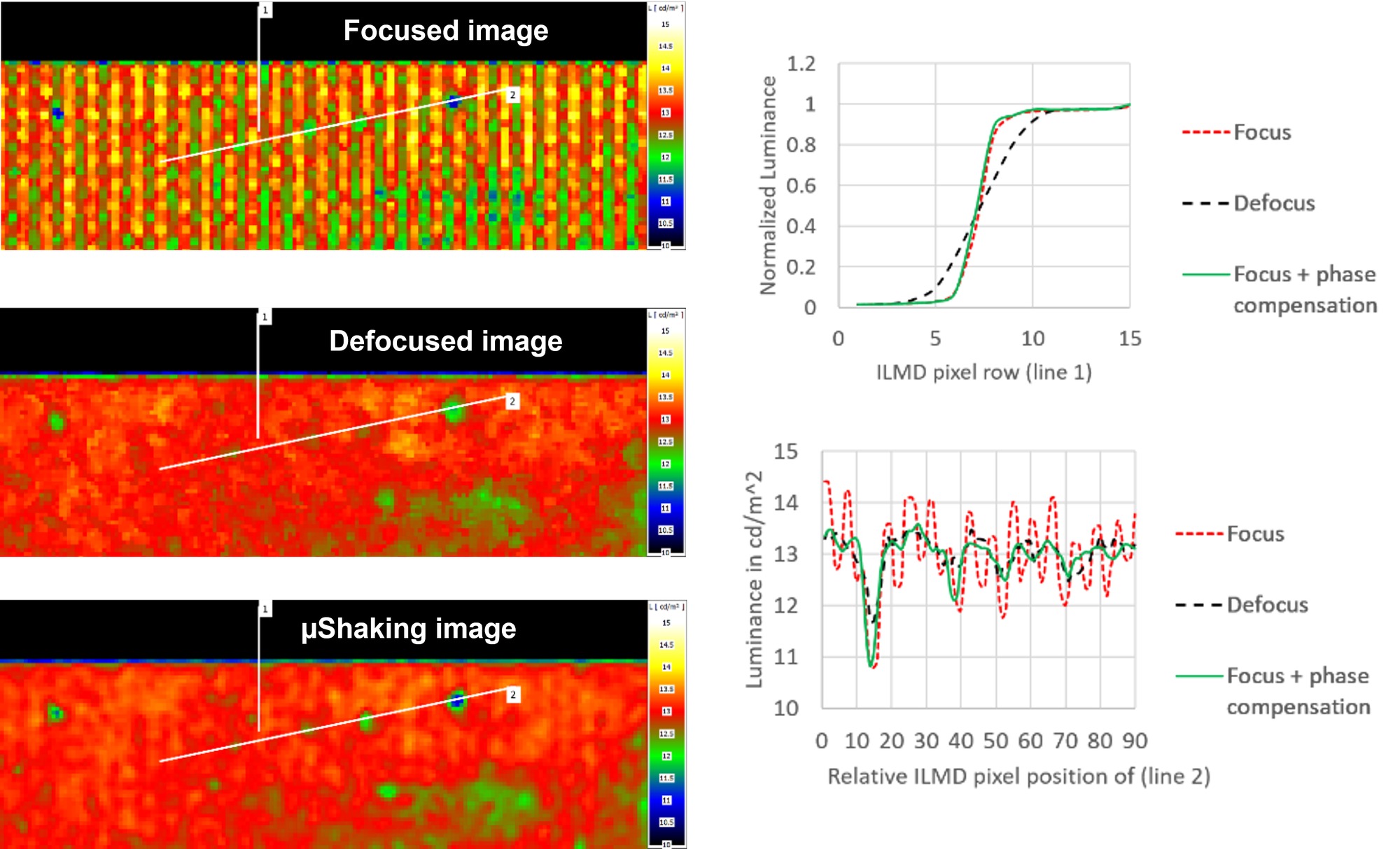
Left column: the same panel captured three ways — focused (Moiré clearly visible), defocused (Moiré suppressed, but fine detail smeared), µShaking (focus with phase compensation — Moiré suppressed, detail preserved). Right column: two quantitative verifications along the lines annotated in the captures. Top graph — normalised luminance across a sharp edge on line 1 — focused and µShaking track each other, the defocused curve flattens the edge. Bottom graph — luminance in cd/m² along line 2 in a nominally uniform area — the focused measurement shows the Moiré oscillation, the defocused measurement suppresses Moiré but also washes out the fine structure, and µShaking returns a flat profile at the expected luminance.
With µShaking, APR works at approximately 2–3 camera pixels per display pixel, instead of the ~10 cpx/dpx typically needed without — enabling smaller ROIs and denser panels at the same working distance.
Patented correction-data-from-µShaking workflow
The method of deriving correction data from µShaking measurements — so that the subsequent routine measurement runs without shaking — is covered by TechnoTeam's international patent family (e.g. US 12,387,297 B2). The panel is characterised once via µShaking; the derived correction data then lets the line camera operate shake-free in routine production — a key enabler for DeMura on lines with permanent vibrations.
The DeMura production workflow
On the production line, TechnoTeam's DeMura correction workflow runs in three stages:
- Teach (first panel of a batch only) — APR teaches the sub-pixel emitter position on the first panel. Where Moiré is a concern, µShaking is run on this first panel too, so the patented correction data can be derived.
- Acquire (every DUT) — each subsequent DUT is captured with one image per test input signal using SPR. Multiple grey levels require one image per grey level per DUT. µShaking does not need to be re-run — the derived correction data takes over.
- Generate — the LMK DeMURA software computes per-emitter correction coefficients from the acquired luminance data and exports the correction data files.
The workflow runs on each LMK and integrates into the line via TCP/IP. For lab-side APR stitching and characterisation, the same camera runs under LabSoft.
FAQ - DeMura, APR and µShaking
Does APR require a geometrically calibrated LMK?
No. APR is a pure software workflow and does not require geometric calibration. If your application also needs absolute position accuracy across the image field, the optional Type II calibration (photometric + geometric) is available.
Does TechnoTeam also write the correction data back to the panel?
No. TechnoTeam delivers the correction data files in the format specified for your panel. Writing the coefficients into the panel's correction memory is handled by the panel maker's programming tools, outside TechnoTeam's scope.
When should I use SPR instead of full APR?
SPR is built for production lines where the same display type is measured repeatedly, ILMD settings are stable, and DUT positions vary only slightly. Under those conditions SPR matches full APR in luminance accuracy (Q ≥ 0.98) while saving the registration capture on every DUT. For lab characterisation and one-off measurements, use full APR.
What is segmented capture, and why APR/SPR instead?
Segmented capture is the prior state-of-the-art DeMura method: for a given test input signal, only every n-th pixel in each row and column is switched on, and the camera takes n² sequential images — shifting the lit pattern each time — to recompose a full-resolution luminance map. It still requires defocus, alters the panel's average load and scales as n² images per test input signal. APR and SPR replace this with one registration image plus one luminance image per test input signal (SPR: just the luminance image after teaching) — full resolution preserved, optional defocus or µShaking, no n² scaling.
Permanent vibrations are critical in my production environment — do I always need µShaking during routine measurement?
No. TechnoTeam's patented method (e.g. US 12,387,297 B2) derives correction data from µShaking measurements so that subsequent routine measurements run shake-free. You characterise the panel once with µShaking; routine in-line measurements then use the derived correction data without activating the stage.
When is µShaking mandatory?
When the native sampling ratio cannot be increased past ~10 cpx/dpx — typically on dense OLED / µLED / Micro-LED panels, or when a given lens/working distance must be preserved. µShaking lets APR run at ~2–3 cpx/dpx.
RELEVANT PRODUCTS
RELEVANT PUBLICATIONS
Invited Paper: Reproducible Characterization of Microdisplays using Imaging Luminance Measurement Devices (ILMDs)
International Conference on Display Technology (ICDT 2024)
In this contribution, we present typical practical implications of high magnification lenses required for camera-based microdisplay measurements and analyze their impact on existing measurement methods for DeMURA, resolution and contrast. Furthermore, we show hardware and software-based methods to improve or handle the shortcomings of these high-magnification lenses.
Invited Paper: Fast and Robust High Precision Luminance Image Stitching in Uniformity and DeMURA measurements
International Conference on Display Technology (ICDT 2023)
This paper provides an overview of image stitching and its general advantages and challenges. Further, we introduce a novel stitching concept based on our advanced pixel registration (APR) procedure. It allows easy and comparable flexible stitching setups for DeMURA and uniformity measurements in laboratory and production environments.
Fast and Accurate Acquisition of Pixel-Level Luminance DeMURA-Data for Curved and Freeform Displays
International Meeting on Information Display (IMID 2022)
Modern single-pixel emitter displays such as OLED, MicroLEDs and LEDs suffer from production-related non-uniformity. The luminance and chromaticity can vary locally from pixel to pixel, resulting in a high-frequency non-uniformity and globally leading to a low-frequency non-uniformity. In order to correct these effects, luminance data of individual subpixels need to be measured. However, this is a very challenging and time-consuming task, especially for modern high-resolution displays.
To ensure a correct pixel registration (assigning the luminance to the correct pixel) in state of the art methods, display pixels are partially switched off [Patent US9135851B2]. However, this reduces cycle time and changes the average pixel level, which can affect the results.
We present a method to overcome these issues, called Advanced Pixel Registration (APR). It is based on a specific registration pattern applied during a teach-in process. An example pattern is provided in Figure 1 (left). After this initial registration, DeMURA measurements can be performed with only one image capture per input signal. The same is true for following displays during EOL testing, as small misalignments, which occur in production control environments as slight shifts, inclinations or rotations of the DUT (see Figure 2) can be corrected automatically.
This contribution validates the APR method using a flat and free-form curved display with methods similar to [] Feng, X. (2019), 78-2: Measurement and Evaluation of Subpixel Brightness for Demura. SID Symposium Digest of Technical Papers, 50: 1122-1125.]. The results show that the APR method can significantly improve the efficiency of DeMURA processes required for high-quality LED, OLED and MicroLED displays, regardless of their shape.
High-Precision High-Resolution Measurements within Moiré
Society for Information Display 2022
Evaluation of single emitter-based display technologies like OLED and μLED at modern display resolutions requires high-resolution measurements. The typically used oversampling often negatively affect cycle times and ILMD complexity. In this contribution, we present, explain, and validate an alternative to performing high-resolution measurements despite the Moiré phenomenon.
Towards High Precision One Shot EOL Testing for Acquiring Pixel Level Luminance Data
International Conference on Display Technology (ICDT 2021)
In this contribution, we present and validate a DeMURA procedure using a one-shot approach that does not require massive oversampling. It bases on on-site calibration of the imaging condition in the setup by a specific teach pattern. It has only to be performed for the first sample. Slight misalignments of following displays are then automatically corrected. After that, the luminance of each display can be measured with a single measurement. The proposed method has the potential to facilitate high-precision calibration of pixel-level luminance under much more relaxed sampling conditions and higher speed compared to current methods.