Automotive Cockpit Display Metrology
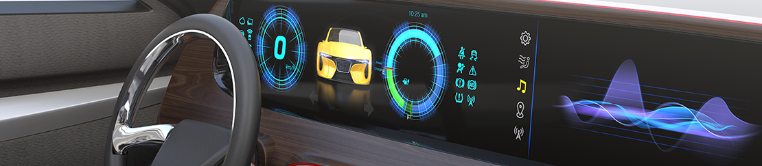
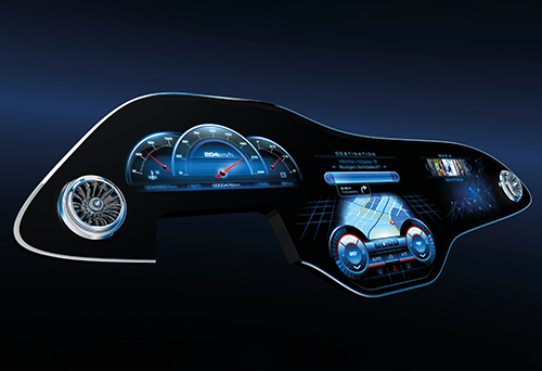
Displays in cars serve as instrument clusters (IC) or head-up displays (HUD) to show important information to the driver, as central information displays (CID), or as passenger or rear seat displays for entertainment. Sometimes they even replace mirrors and serve as camera surveillance displays. Especially in cars, there are no limits to form factors and 3D shapes. They sometimes have various features such as image enhancement, privacy modes or anti-glare features. All of these displays must be of high quality to withstand significant temperature differences, vibrations and shocks and need to display content under changing lighting conditions. They must also be able to be viewed from different angles to accommodate different sizes, positions, and passengers.
Measurement tasks
The German Flat Panel Display Forum (Deutsches Flachdisplay Forum, external link), a leading expert network in the field of displays, has developed recommendations for automotive displays together with the OEM working group. These include specification values and methods for optical tests. They apply to all types of automotive displays. Examples are:
- OEM Specification
- DFF OLED Specification
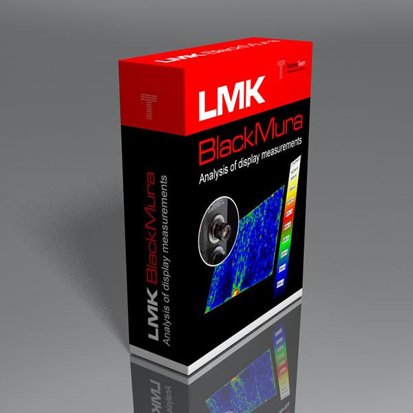
- DFF BlackMURA
- DFF Gamma
- DFF Sticking Image (3-level)
- Angular OEM Regions


Premium manufacturers in particular have drawn up additional specifications to ensure readability and the highest optical quality. Many of these measurements were developed, evaluated and/or researched in projects together with TechnoTeam. These include, for example the following measurement tasks:
- Display Sparkle for anti glare layers (AGL)
- Sticking Image (2-level)
- Reflection for contrast under ambient light (sun light)
- Resolution by Pixel Cross Talk and Slanted Line MTF (Modulation Transfer Function)
- Halo for Full-Array Local Dimming Display (FALD)
- Any measurement item from a vantage point as e.g. driver and passenger
Our solutions
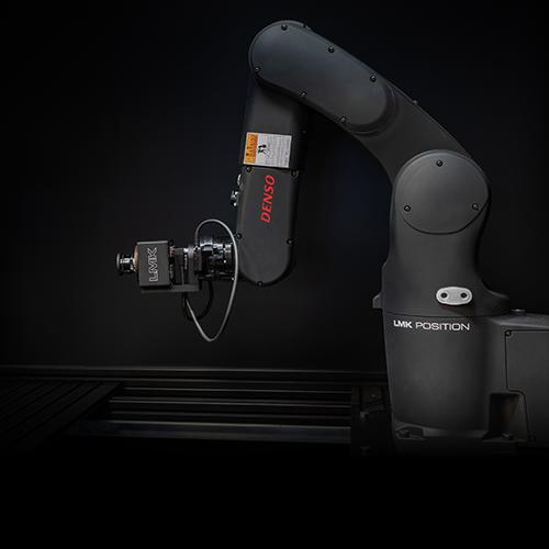
TechnoTeam offers a wide array of lenses and specialized add-ons to ensure fast and reproducible measurements according to all these requirements and methods. Our dedicated robotic-based ILMD system, the LMK Position - can ensure fast and highly reproducible alignment of various shapes, including ultra-wide screens and free-form shapes common in modern cars. For more information on the specific products and applications, please refer to the dedicated information shown below:
FAQ — Automotive Display: Optical Testing for In-Vehicle Displays
Automotive displays operate under conditions that consumer or industrial devices rarely encounter: wide temperature ranges, vibration, shock, ambient light from full sunlight to darkness, long static-content exposure, anti-glare layers on the cover glass, and viewing from multiple seating positions rather than a single perpendicular eye position. Modern and premium displays add free-form geometries, deep integration into the interior, and specialty technologies such as hidden displays (so-called Shy-Tech concepts) that look like a plain interior panel until activated. Generic consumer-display tests do not cover these challenges, which is why the automotive industry has developed dedicated specifications and measurement procedures.
The scope covers all in-vehicle displays — instrument clusters, head-up displays, central information displays, passenger and rear-seat entertainment screens, and the camera surveillance displays that replace conventional mirrors — including flat, curved, free-form, and ultra-wide pillar-to-pillar layouts. A more recent extension is exterior displays such as digital signage surfaces on the vehicle body; these require evaluation under outdoor ambient-light conditions and can be measured with the same instruments.
Optical testing of an automotive display can be grouped into five dimensions:
- Spatial uniformity — low-frequency variation captured by the BlackMURA workflow, high-frequency variation from anti-glare layers captured as display sparkle.
- Temporal stability — sticking-image and burn-in evaluations that quantify how static content affects the panel over time.
- Ambient-light performance — reflection measurements together with ISO 15008-style contrast to predict readability under sunlight.
- Resolution — Pixel Cross Talk and Slanted Line MTF.
- Angular behavior — conoscopic measurement of luminance and contrast across the angular regions defined in OEM specifications.
The dedicated product pages contain the methodical detail.
The German Flat Panel Forum is an expert network of display manufacturers, automotive OEMs, and testing companies. The DFF maintains a set of automotive display specifications, including DFF BlackMURA, DFF Gamma, DFF Sticking Image at three grey levels, and the DFF OLED specification. BlackMURA, DFF Gamma, and the companion OEM specification were developed jointly with the German automotive OEM working group; other DFF documents have been authored within the DFF itself. The OEM specification additionally contains the definitions of the angular regions used for viewing-angle evaluation. Together, these documents form the common technical baseline that OEMs, suppliers, and test labs share when qualifying automotive displays, and they are the reference that the corresponding TechnoTeam products implement.
Many of the measurement procedures referenced on this application page were developed, validated, or refined in joint projects with TechnoTeam, and a selection of these results is documented in publicly available conference and journal papers co-authored with the partners. The BlackMURA workflow for low-frequency uniformity was developed in close collaboration with the German automotive OEM working group and the DFF. The sparkle evaluation that became the basis of the automotive sparkle specification was co-published with Volkswagen and validated in a multi-laboratory round-robin experiment (DOI 10.1002/jsid.1169). Pixel Cross Talk as a metric for anti-glare-related resolution loss was co-published with Porsche (DOI 10.1002/sdtp.10682). Reflection and ISO 15008-style ambient-light contrast procedures were co-published with Mercedes-Benz (DOI 10.1002/msid.1549). The Slanted Line MTF method was jointly adopted for automotive applications and co-published with Continental (Eurodisplay Stuttgart 2022, ResearchGate). The extension of the DFF documents toward OLED was prepared together with DFF members.
The DFF and the OEM working-group documents define a shared baseline. Premium manufacturers can extend this baseline to safeguard readability and the highest perceived optical quality of their interior. Topics that can appear in these additional specifications include display sparkle for anti-glare layers, sticking image at two grey levels, reflection under sun-like ambient light, resolution by Pixel Cross Talk and Slanted Line MTF, halo evaluation for full-array local dimming displays, and measurements from defined vantage points such as the driver and the front passenger. These topics map directly onto the corresponding TechnoTeam products and add-ons.
Form factors that depart from a flat panel create two challenges at once: the device under test no longer sits in a single focal plane, and a single image often cannot cover the full display area at the required sampling. The robotic LMK Position system addresses the first challenge by automatically aligning the imaging luminance camera to a sequence of measurement points across curved and free-form geometries. LMK Stitching addresses the second challenge by fusing overlapping captures into one high-resolution image with consistent geometry. For uniformity measurements that would require impractically long measurement distances, an alternative short-distance procedure has been developed.
Two related alignment challenges are common in automotive display testing: prototypes rarely come with standardized fixtures, and many measurements have to be performed from defined eye positions such as driver and front passenger rather than perpendicular to the display. The LMK Position platform handles both. Alignment is vision-based, so the camera moves to the display rather than the display being forced into a predefined position — arbitrary holders, customer mock-ups, and loose prototypes can be used without re-tooling. The same robotics also moves the camera to defined vantage points under reproducible kinematics, independent of operator and fixture; this also applies to split-view displays, where driver- and passenger-visible content differ by design and have to be evaluated separately. The general concept is documented as photometric robotics in the literature.
Full-Array Local Dimming (FALD) improves contrast and reduces power consumption of LCDs by switching individual backlight zones. The flip side is halo: bright content can spill into surrounding dark areas where adjacent zones overlap, which affects readability of instrument-cluster content and the perceived quality of dark-background layouts. For automotive use, the DFF runs a dedicated FALD working group that defines how halo should be quantified and at which thresholds it becomes visible to the viewer. TechnoTeam contributes to this scientific work by carrying out metrological and perceptual investigations.
The platform covers all three deployment scenarios. In the lab, a single LMK camera with interchangeable lenses handles the full automotive task list: standard lenses for full-display BlackMURA, sparkle, sticking image, halo, and image stitching; the conoscopic lens for viewing-angle and reflection measurements; and macro or micro lenses for resolution by Pixel Cross Talk and Slanted Line MTF. For alignment-critical tasks on curved, free-form, or ultra-wide displays and for vantage-point measurements, the same camera is mounted on LMK Position. In production and end-of-line, the same LMK hardware is paired with dedicated software that can be operated in GUI mode or via TCP/IP for integration into MES/PLC environments — so BlackMURA and LMK DeMURA-type uniformity correction run on the same measurement principle as in the lab. The Display Package bundles these modules and receives further add-ons as OEM and DFF specifications evolve; the robotic alignment additionally integrates a spectroradiometer at the same poses as the imaging luminance measurements. The result is a methodically consistent test chain from R&D through qualification to series production that remains extensible to new measurement tasks without replacing core hardware.
RELEVANT PRODUCTS
RELEVANT PUBLICATIONS
16. International Symposium on Automotive Lighting
Journal of the Society for Information Display
SID 2025
IDW 2024
Society for Information Display 2025
Information Display 2025
International Display Workshop (IDW 2023)
International Conference on Display Technology (ICDT 2023)
Journal of the Society for Information Display
International Conference on Display Technology (ICDT 2021)
Journal of the Society for Information Display
SID Vehicle Displays & Interfaces 2021
electronic displays Conference 2016
SID Vehicle Displays & Interfaces 2019
This contribution concentrates on the performance of two selected image sticking evaluation methods [5, 6] from the automotive community and [1] for reference. After briefly introducing the three methods, this contribution focusses on their capability of separating initial non-uniformities from the actual sticking image effect of the target display. Therefore, a mathematical analysis, which is based on a simple but physically motivated sticking image model, is performed. Based on that, an additional non-uniformity correction is proposed. This additional correction has a positive influence on the precision but a negative influence on the measurement time of the fastest measurement method [6]. Thus, we propose a workflow, that decides based on the properties of the DUT whether the correction is necessary or not. All conclusions are supported by simulations and validated using measurement results of a randomly chosen non-uniform automotive LC display.
The aim of this paper is on the one hand to quantize the mathematical influence of the methods and on the other hand to suggest a workflow, which utilizes an existing method and optimizes its application with respect to precision and overall measurement time.
SID Vehicle Displays & Interfaces 2018
Based on the general working principle of ILMDs (imaging luminance measurement device), we briefly explain typical ILMD characteristics as well as the concepts of repeatability, reproducibility, precision and measurement uncertainty [1]. Afterwards, optical display properties as well as measurement methods [2, 3, 4] are introduced.
Finally, we qualitatively and quantitatively assess chosen influences of ILMD specifications and different measurement procedures on the obtained results.
Thus, this work shall convey a feeling for photometric display metrology requirements under the consideration of the measurement task and the desired precision