Automotive-Cockpit-Display-Messtechnik
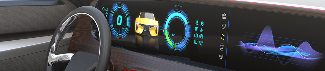
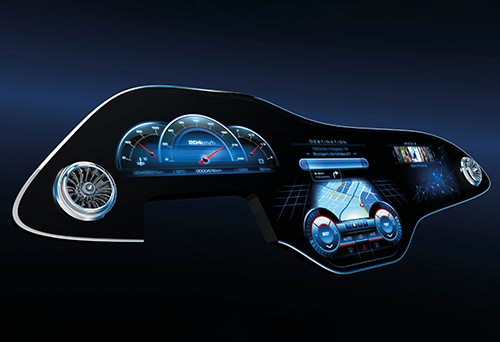
Displays in Fahrzeugen dienen als Kombiinstrument (IC) oder Head-up-Display (HUD), um dem Fahrer wichtige Informationen anzuzeigen, als zentrale Informationsanzeigen (CID) oder als Beifahrer- oder Rücksitz-Displays zur Unterhaltung. Teilweise ersetzen sie sogar die Seitenspiegel. In Fahrzeugen sind dem Design und den Formfaktoren der Displays keine Grenzen gesetzt (Curved Displays). Sie verfügen teilweise über verschiedene Funktionen wie Bildoptimierung, Privatsphäre-Modi und Entspiegelung. Die Displays müssen großen Temperaturunterschieden, Vibrationen und Erschütterungen standhalten und gut lesbare Inhalte unter wechselnden Lichtverhältnissen anzeigen. Außerdem müssen sie aus verschiedenen Blickwinkeln gut lesbar sein, um Menschen verschiedener Größe und von unterschiedlichen Sitzpositionen aus einen guten Ablesekomfort zu bieten.
Messaufgaben
Das Deutsche Flachdisplay Forum (externer Link), ein führendes Expertennetzwerk im Bereich Displays, hat zusammen mit der Arbeitsgruppe OEM Empfehlungen für Automobildisplays entwickelt. Diese umfassen Spezifikationswerte und Methoden für optische Tests. Sie gelten für alle Arten von automobilen Displays. Beispiele sind:
- OEM Spezifikationen
- DFF OLED Spezifikationen
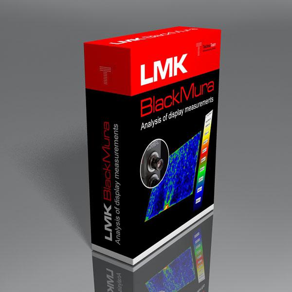
- DFF BlackMURA
- DFF Gamma
- DFF Sticking Image (3-level)
- Winkelbereiche der OEMs


Insbesondere Premium-Hersteller haben zusätzliche Spezifikationen erstellt, um die Lesbarkeit und höchste optische Qualität zu gewährleisten. Viele dieser Messungen wurden in Projekten zusammen mit TechnoTeam entwickelt, bewertet und/oder erforscht. Dazu gehören zum Beispiel:
- Display Sparkle für Anti-Glare-Schichten (AGL)
- Sticking Image (2-level)
- Reflexion für Kontrast bei Umgebungslicht
- Auflösung durch Pixel Cross Talk oder Modulationsübertragungsfunktion
- Halo für Full-Array-Local-Dimming Display (FALD)
- Alle vorherigen Messungen aus Fahrer-/Beifahrerposition
Unsere Lösung
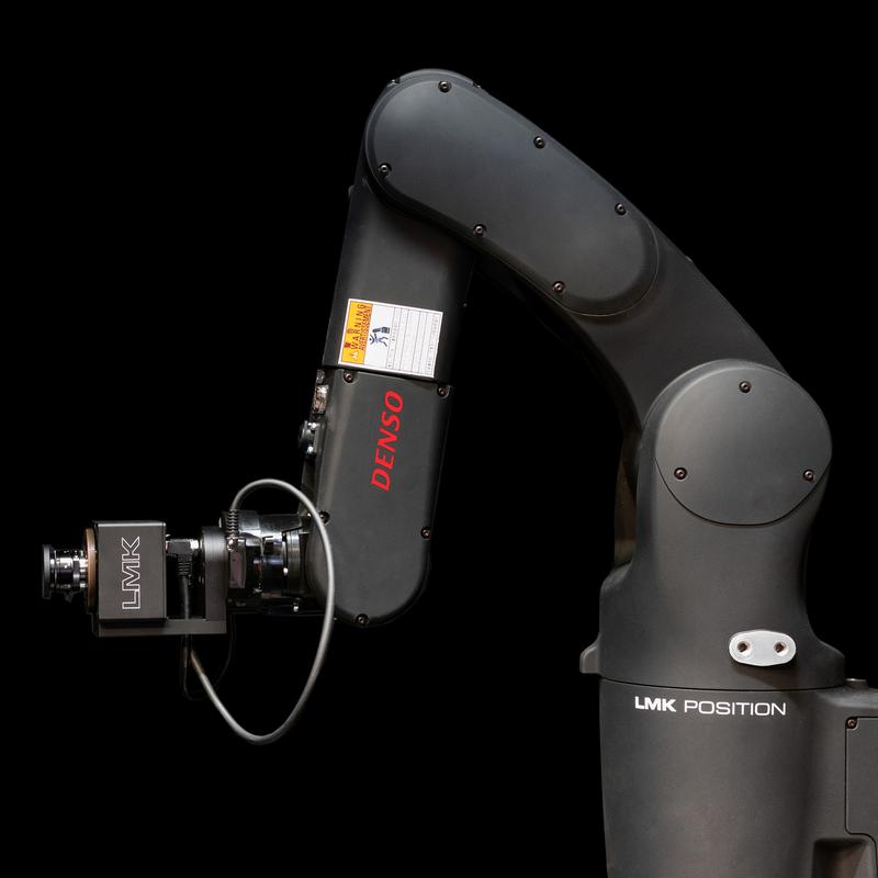
TechnoTeam bietet eine Vielzahl von speziellen Hard- und Softwarelösungen an, um schnelle und reproduzierbare Messungen gemäß all diesen Spezifikationen und Methoden zu gewährleisten. Das LMK Position ist ein spezielles roboterbasiertes System für unsere Leuchtdichtemesskameras, das eine schnelle und äußerst reproduzierbare Ausrichtung an Displays mit verschiedenen Geometrien — auch bei Blickwinkeln — gewährleistet, einschließlich ultrabreiter Bildschirme und Freiformflächen, wie sie in modernen Autos üblich sind. Weitere Informationen zu den einzelnen Produkten und Anwendungen finden Sie in den nachstehenden Links:
FAQ — Automotive Display: Optische Prüfung von Fahrzeugdisplays
Automotive-Displays arbeiten unter Bedingungen, denen Consumer- oder Industriegeräte nur selten ausgesetzt sind: große Temperaturbereiche, Vibration, Erschütterungen, Umgebungslicht von vollem Sonnenlicht bis zur Dunkelheit, lange Standzeiten statischer Inhalte, Anti-Glare-Schichten auf dem Deckglas und die Betrachtung aus mehreren Sitzpositionen statt aus einer einzigen senkrechten Augenposition. Moderne und Premium-Displays bringen zusätzlich Freiformgeometrien, eine tiefe Integration in den Innenraum und Spezialtechnologien wie versteckte Displays (sogenannte Shy-Tech-Konzepte) mit sich, die bis zur Aktivierung wie eine schlichte Innenraumblende aussehen. Generische Consumer-Display-Tests decken diese Herausforderungen nicht ab, weshalb die Automobilindustrie eigene Spezifikationen und Messverfahren entwickelt hat.
Der Anwendungsbereich umfasst alle Displays im Fahrzeuginnenraum — Kombiinstrumente, Head-up-Displays, Zentraldisplays, Beifahrer- und Rear-Seat-Entertainment-Displays sowie die Kamera-Monitor-Displays, die herkömmliche Spiegel ersetzen — einschließlich flacher, gekrümmter, frei geformter und ultrabreiter Pillar-to-Pillar-Layouts. Eine neuere Erweiterung sind Außendisplays wie Digital-Signage-Flächen an der Fahrzeugkarosserie; diese müssen unter Außenlichtbedingungen bewertet werden und lassen sich mit denselben Geräten vermessen.
Die optische Prüfung eines Automotive-Displays lässt sich in fünf Dimensionen gliedern:
- Räumliche Homogenität — niederfrequente Schwankungen werden über den BlackMURA-Workflow erfasst, hochfrequente Schwankungen durch Anti-Glare-Schichten als Display-Sparkle.
- Zeitliche Stabilität — Sticking-Image- und Burn-in-Bewertungen, die quantifizieren, wie sich statische Inhalte über die Zeit auf das Panel auswirken.
- Verhalten bei Umgebungslicht — Reflexionsmessungen zusammen mit Kontrastbewertungen nach ISO 15008, um die Ablesbarkeit bei Sonneneinstrahlung vorherzusagen.
- Auflösung — Pixel Cross Talk und Slanted-Line-MTF.
- Winkelverhalten — konoskopische Messung von Leuchtdichte und Kontrast über die in den OEM-Spezifikationen definierten Winkelbereiche.
Die jeweiligen Produktseiten enthalten die methodischen Details.
Das German Flat Panel Forum ist ein Expertennetzwerk aus Displayherstellern, Automobil-OEMs und Prüfunternehmen. Das DFF pflegt eine Reihe von Automotive-Display-Spezifikationen, darunter DFF BlackMURA, DFF Gamma, DFF Sticking Image bei drei Graustufen und die DFF-OLED-Spezifikation. BlackMURA, DFF Gamma und die zugehörige OEM-Spezifikation wurden gemeinsam mit dem deutschen Automobil-OEM-Arbeitskreis entwickelt; andere DFF-Dokumente sind innerhalb des DFF selbst entstanden. Die OEM-Spezifikation enthält darüber hinaus die Definitionen der Winkelbereiche, die für die Blickwinkelbewertung verwendet werden. Zusammen bilden diese Dokumente die gemeinsame technische Grundlage, auf die sich OEMs, Zulieferer und Prüflabore bei der Qualifizierung von Automotive-Displays stützen, und sie sind die Referenz, die die entsprechenden TechnoTeam-Produkte umsetzen.
Viele der auf dieser Anwendungsseite genannten Messverfahren wurden in gemeinsamen Projekten mit TechnoTeam entwickelt, validiert oder weiterentwickelt, und eine Auswahl dieser Ergebnisse ist in öffentlich zugänglichen Konferenz- und Fachzeitschriftenbeiträgen dokumentiert, die zusammen mit den Partnern verfasst wurden. Der BlackMURA-Workflow für niederfrequente Homogenität wurde in enger Zusammenarbeit mit dem deutschen Automobil-OEM-Arbeitskreis und dem DFF entwickelt. Die Sparkle-Bewertung, die zur Grundlage der Automotive-Sparkle-Spezifikation wurde, wurde gemeinsam mit Volkswagen veröffentlicht und in einem laborübergreifenden Ringversuch validiert (DOI 10.1002/jsid.1169). Pixel Cross Talk als Metrik für den durch Anti-Glare bedingten Auflösungsverlust wurde gemeinsam mit Porsche veröffentlicht (DOI 10.1002/sdtp.10682). Reflexions- und Umgebungslicht-Kontrastverfahren nach ISO 15008 wurden gemeinsam mit Mercedes-Benz veröffentlicht (DOI 10.1002/msid.1549). Die Slanted-Line-MTF-Methode wurde gemeinsam für Automotive-Anwendungen übernommen und zusammen mit Continental veröffentlicht (Eurodisplay Stuttgart 2022, ResearchGate). Die Erweiterung der DFF-Dokumente in Richtung OLED wurde gemeinsam mit DFF-Mitgliedern erarbeitet.
Die DFF- und die OEM-Arbeitskreis-Dokumente definieren eine gemeinsame Grundlage. Premium-Hersteller können diese Grundlage erweitern, um die Ablesbarkeit und die höchste wahrgenommene optische Qualität ihres Innenraums sicherzustellen. Themen, die in diesen zusätzlichen Spezifikationen auftauchen können, sind unter anderem Display-Sparkle für Anti-Glare-Schichten, Sticking Image bei zwei Graustufen, Reflexion unter sonnenähnlichem Umgebungslicht, Auflösung mittels Pixel Cross Talk und Slanted-Line-MTF, Halo-Bewertung für Full-Array-Local-Dimming-Displays sowie Messungen von definierten Blickpunkten aus, etwa von Fahrer und Beifahrer. Diese Messaufgaben lassen sich direkt den entsprechenden TechnoTeam-Produkten und Add-ons zuordnen.
Bauformen, die vom flachen Panel abweichen, schaffen zwei Herausforderungen auf einmal: Der Prüfling liegt nicht mehr in einer einzigen Fokusebene, und eine einzelne Aufnahme kann die gesamte Displayfläche oft nicht mit der erforderlichen Abtastung erfassen. Das robotergestützte System LMK Position löst die erste Herausforderung, indem es die bildgebende Leuchtdichtekamera automatisch auf eine Abfolge von Messpunkten über gekrümmte und frei geformte Geometrien ausrichtet. LMK Stitching löst die zweite Herausforderung, indem es überlappende Aufnahmen zu einem hochauflösenden Bild mit konsistenter Geometrie zusammenfügt. Für Homogenitätsmessungen, die unpraktikabel große Messabstände erfordern würden, wurde ein alternatives Nahbereichsverfahren entwickelt.
Bei der Prüfung von Automotive-Displays treten häufig zwei verwandte Ausrichtungsprobleme auf: Prototypen werden nur selten mit standardisierten Aufnahmevorrichtungen geliefert, und viele Messungen müssen aus definierten Augenpositionen wie Fahrer und Beifahrer statt senkrecht zum Display erfolgen. Die Plattform LMK Position bewältigt beides. Die Ausrichtung erfolgt bildbasiert: Die Kamera fährt zum Display hin, statt das Display in eine vorgegebene Position bringen zu müssen — beliebige Halterungen, Kunden-Mock-ups und lose Prototypen lassen sich ohne Umrüstung verwenden. Dieselbe Robotik bewegt die Kamera zudem mit reproduzierbarer Kinematik zu definierten Blickpunkten, unabhängig von Bediener und Vorrichtung; das gilt auch für Split-View-Displays, bei denen sich die für Fahrer und Beifahrer sichtbaren Inhalte konstruktionsbedingt unterscheiden und separat bewertet werden müssen. Das allgemeine Konzept ist in der Literatur als Photometric Robotics dokumentiert.
Full-Array Local Dimming (FALD) verbessert den Kontrast und senkt den Stromverbrauch von LCDs, indem einzelne Backlight-Zonen separat angesteuert werden. Die Kehrseite ist der Halo-Effekt: Helle Inhalte können in angrenzende dunkle Bereiche überstrahlen, wo benachbarte Zonen aneinandergrenzen. Das beeinträchtigt die Ablesbarkeit von Kombiinstrument-Inhalten und die wahrgenommene Qualität von Layouts mit dunklem Hintergrund. Für den Automotive-Einsatz betreibt das DFF einen eigenen FALD-Arbeitskreis, der festlegt, wie Halo quantifiziert wird und ab welchem Schwellenwert es für den Betrachter sichtbar wird. TechnoTeam wirkt an dieser wissenschaftlichen Arbeit mit, indem es messtechnische und wahrnehmungsphysiologische Untersuchungen durchführt.
Die Plattform deckt alle drei Einsatzszenarien ab. Im Labor bewältigt eine einzige LMK-Kamera mit Wechselobjektiven die gesamte Automotive-Aufgabenliste: Standardobjektive für BlackMURA über das gesamte Display, Sparkle, Sticking Image, Halo und Image Stitching; das konoskopische Objektiv für Blickwinkel- und Reflexionsmessungen; sowie Makro- oder Mikroobjektive für die Auflösung mittels Pixel Cross Talk und Slanted-Line-MTF. Für ausrichtungskritische Aufgaben an gekrümmten, frei geformten oder ultrabreiten Displays sowie für Messungen von Blickpunkten aus wird dieselbe Kamera auf LMK Position montiert. In Produktion und End-of-Line wird dieselbe LMK-Hardware mit dedizierter Software kombiniert, die im GUI-Modus oder über TCP/IP für die Integration in MES-/SPS-Umgebungen betrieben werden kann — sodass BlackMURA und Homogenitätskorrekturen vom Typ LMK DeMURA nach demselben Messprinzip ablaufen wie im Labor. Das Display Package bündelt diese Module und erhält weitere Add-ons, sobald sich OEM- und DFF-Spezifikationen weiterentwickeln; die robotergestützte Ausrichtung integriert zusätzlich ein Spektroradiometer an denselben Posen wie die bildgebenden Leuchtdichtemessungen. Das Ergebnis ist eine methodisch konsistente Prüfkette von der Entwicklung über die Qualifizierung bis zur Serienproduktion, die sich ohne Austausch der Kern-Hardware um neue Messaufgaben erweitern lässt.
RELEVANTE PRODUKTE
RELEVANTE PUBLIKATIONEN
16. International Symposium on Automotive Lighting
Journal of the Society for Information Display
SID 2025
IDW 2024
Society for Information Display 2025
Information Display 2025
International Display Workshop (IDW 2023)
International Conference on Display Technology (ICDT 2023)
Journal of the Society for Information Display
International Conference on Display Technology (ICDT 2021)
Society for Information Display
Society for Information Display
SID Vehicle Displays & Interfaces 2021
Electronic Display Conference 2016
SID Vehicle Displays & Interfaces 2019
This contribution concentrates on the performance of two selected image sticking evaluation methods [5, 6] from the automotive community and [1] for reference. After briefly introducing the three methods, this contribution focusses on their capability of separating initial non-uniformities from the actual sticking image effect of the target display. Therefore, a mathematical analysis, which is based on a simple but physically motivated sticking image model, is performed. Based on that, an additional non-uniformity correction is proposed. This additional correction has a positive influence on the precision but a negative influence on the measurement time of the fastest measurement method [6]. Thus, we propose a workflow, that decides based on the properties of the DUT whether the correction is necessary or not. All conclusions are supported by simulations and validated using measurement results of a randomly chosen non-uniform automotive LC display.
The aim of this paper is on the one hand to quantize the mathematical influence of the methods and on the other hand to suggest a workflow, which utilizes an existing method and optimizes its application with respect to precision and overall measurement time.
SID Vehicle Displays & Interfaces 2018
Based on the general working principle of ILMDs (imaging luminance measurement device), we briefly explain typical ILMD characteristics as well as the concepts of repeatability, reproducibility, precision and measurement uncertainty [1]. Afterwards, optical display properties as well as measurement methods [2, 3, 4] are introduced.
Finally, we qualitatively and quantitatively assess chosen influences of ILMD specifications and different measurement procedures on the obtained results.
Thus, this work shall convey a feeling for photometric display metrology requirements under the consideration of the measurement task and the desired precision