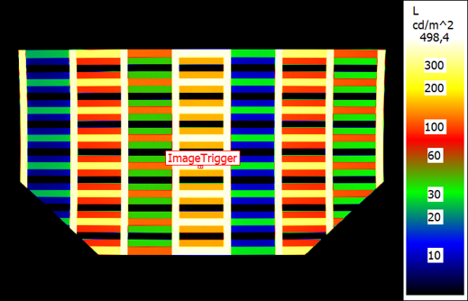
Three-level burn-in pattern for color image sticking measurement with our image-content trigger setup
LMK Sticking Image: Burn-In & Image Retention Testing
Image retention, ghosting, and burn-in are critical concerns in display quality and durability. These phenomena impact performance, lifetime, and visual quality. The LMK Sticking Image Add-on provides a precise, standardized method to measure these effects, and it can be integrated into existing measurement workflows. LMK Sticking Image can be used for LCDs and OLEDs as well as other technologies prone to image sticking, especially in applications showing static or partially static content, e.g. automotive, aviation and public-information displays.
Patented Content-Based Trigger & Measurement Methodology
The LMK 5 and current LMK 6 imaging photometers and colorimeters, together with LabSoft, can run image sticking test series out of the box. A display under test is exposed to a burn-in phase with defined patterns, followed by relaxation phases in which the time-resolved luminance distribution is recorded.
Used with an LMK 6 system, the add-on unlocks our content-based trigger: the LMK camera itself optically observes a freely adjustable region of the burn-in pattern at very high frequency and detects the moment of pattern switching. This well-defined reference point aligns every relaxation measurement with the displayed content — independent of device-, cable- or PC-specific input lags — and without any external photodiode or trigger hardware. The trigger method for image sticking is covered by TechnoTeam's international patent family (e.g. US 11,557,111 B2).
Two- and Three-Level Evaluation Procedures for Reliable Results
Our LMK Sticking Image add-on can be used to analyze the display burn-in behavior according to two established procedures:

Burn-in pattern and relaxation images of a three-level measurement series
Three-level approach by Dr. Lauer
- Can be extended to color image sticking
- Method adapted by the German Flat Panel Display Forum (DFF)
- Local or temporal non-uniformity correction possible

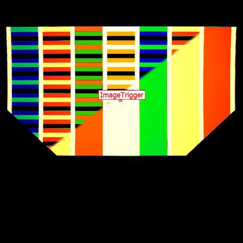
Burn-in pattern and relaxation images of a two-level measurement series
Two-level approach by Dr. Bauer
- Including automatic pattern rolling for warm-up
- Classical checkerboard burn-in pattern
- High-precision temporal non-uniformity correction
Advantages of LMK Sticking Image
- Fast and precise measurement of image retention effects
- Patent-protected trigger method for reliable synchronization
- Flexible evaluation procedures (two-level, three-level, custom setups)
- Seamless integration with existing LMK measurement setups
- Compliance with established standards — DFF (3-level) and OEM (2-level) methods
Integration and Related Solutions
LMK Sticking Image is part of the TechnoTeam Display Package, ensuring compatibility with other LMK-based measurement solutions.
FAQ — Sticking Image
What is LMK Sticking Image?
LMK Sticking Image is an add-on for TechnoTeam's LMK imaging photometers and colorimeters that runs inside LabSoft. It quantifies the permanent burn-in or the reversible image sticking, which is also called image retention or ghosting. Both effects can appear on displays that show static or partially static content. The evaluation result is a time-resolved image sticking value in percent. The add-on is part of the TechnoTeam display package.
The add-on provides the complete measurement and evaluation procedures of two established measurement methods, the three-level approach after Dr. Lauer and the two-level approach after Dr. Bauer.
What does a complete measurement series look like?
A series consists of a warm-up phase, a burn-in phase and a relaxation phase, executed back to back. During warm-up the display is driven with changing content so that it reaches a steady state and recovers from any earlier image sticking. During burn-in it shows the chosen burn-in pattern for the agreed burn-in time. During relaxation the burn-in pattern is replaced by the relaxation image, and the luminance distribution is measured repeatedly while the effect decays.
With the display connected directly to LabSoft, LabSoft presents the test images itself and runs the whole series automatically. Where the test images are switched from outside, by a pattern generator or by the customer's own test system, LabSoft guides through the measurement sequence just the same.
Which camera, software and lens do I need?
The add-on runs on LMK imaging photometers and colorimeters together with LabSoft. An LMK 5 covers the complete measurement and evaluation procedures. An LMK 6 adds two functions: the patented content-based trigger, which synchronises the start of the relaxation measurement with the actual pattern switch on the display, and area-of-interest readout, or AOI, which speeds up the temporal readout and reduces the amount of data. Each of the two runs natively on every LMK 6 system.
The lens comes from the standard LMK range, the same lenses that are used for other automotive display measurements such as BlackMURA and sparkle. The choice is decided by the field of view: image sticking is evaluated on comparatively large fields but across the full panel, so the whole display has to fit in the image.
What is the patented content-based trigger, and why does it matter?
In the naive setup the host PC sends the new test image to the display and starts the image acquisition immediately afterwards. Between those two events lies an input lag that can depend on the computer, on the video interface, on the system controller and on the internal video processing of the panel, and that lag is normally unknown. Start too early and parts of the burn-in pattern are evaluated by accident, which makes the reported value too high. Start too late and the initial level of image sticking has already begun to decay, which makes it too low.
The content-based trigger removes that uncertainty. The camera itself watches a freely adjustable region of the burn-in pattern at very high frequency, detects the moment of pattern switching optically, and every relaxation measurement is referenced to that moment with a freely chosen delay. Whatever the input lag of a given setup happens to be, the reference point is the switch itself, so the signal chain does not have to be characterised beforehand and nothing has to be re-checked when the setup or the display changes. No external photodiode and no auxiliary trigger hardware are needed. The method is covered by TechnoTeam's international patent family, for example US 11,557,111 B2.
What is the difference between the two-level and the three-level approach, and when do I use which?
The two procedures differ in their burn-in pattern, and from that follows how each separates the display's own non-uniformity from the image sticking effect.
The two-level approach after Dr. Bauer burns in a checkerboard of two grey levels and evaluates the effect on a uniform relaxation image. Its non-uniformity correction is temporal: a reference image at the relaxation grey level is captured before burn-in and compared with the relaxation image afterwards. That reference capture presupposes a warm-up phase, because the display has to be in a steady state when it is taken.
The three-level approach after Dr. Lauer uses a burn-in pattern with three levels, one of which is the relaxation grey level itself. Those fields see no burn-in and therefore act as a local reference inside the relaxation image, so no reference capture before burn-in is needed. This is what allows the warm-up phase to be shortened, and it holds as long as the evaluation stays with the local correction; a temporal correction on the three-level approach needs a reference image and therefore a warm-up phase just like the two-level one. The evaluation is organised column by column, which adds a spatial view of the effect, and allows for color image sticking evaluation. The German Flat Panel Display Forum has adapted the three-level approach.
How long does an image sticking measurement take?
It depends on the procedure. The warm-up time, the burn-in time and the length of the relaxation set the duration of a series. Where those are short the series is short, although several captures are always needed. If the measurement has to run at a specified panel temperature, 65 °C for instance, conditioning the display adds to that.
A series may not be repeatable on the same sample, because a permanent burn-in can remain. The whole procedure therefore has to be settled before the first series starts: grey levels, delays, evaluation regions, correction. There may be no second attempt.
Which grey levels should the burn-in and the relaxation pattern use?
The grey levels used for burn-in and for relaxation have a strong influence on the result, and the default combination of a black and white burn-in evaluated on a mid-grey relaxation image is not the worst case for every panel. On an LCD test display measured at TechnoTeam, the worst combination produced a relative image sticking almost twice as high as the default combination.
A possible way to find it is a pre-test with grey wedges. A horizontal grey wedge serves as the burn-in pattern and a vertical grey wedge as the relaxation pattern, so that one measurement covers all combinations of burn-in and relaxation grey level at once and yields an image sticking grey level combination matrix from which the worst case can be read. A regular two-level or three-level measurement is then run at that operating point. The add-on leaves the choice of grey levels to the user, so the pre-test can be set up as a measurement like any other.
Can image sticking be measured for individual colours?
Yes. The three-level approach extends to colour image sticking directly, with no change to the procedure. The luminance evaluations are then performed for colour test images: the burn-in pattern and the relaxation image are driven in red, green, blue and white, so the relaxation image is no longer uniform. The camera measures luminance throughout, so no imaging colorimeter is needed. The result is one image sticking value per column, where each column corresponds to a different colour.
The extension is most relevant for OLED and MicroLED displays, where the emitters for the individual colours can behave differently.
RELEVANT PRODUCTS AND APPLICATIONS
Publications
Concepts in Image Sticking Measurements: Temporal Alignment, Uniformity Correction and Grey Level Dependency
International Display Workshop (IDW 2020)
This study introduces two proposed Image Sticking evaluation methods from the automotive industry and identifies relevant differences. It further focusses on the importance of precise temporal alignment and outlines the differences between temporal and local non-uniformity corrections as well as grey level dependency. The complete study is based on measured data.
Non-uniformity correction in recent automotive image sticking evaluation methods
SID Vehicle Displays & Interfaces 2019
Modern automotive displays may be sensitive to static content, which remains as an undesired effect of either temporary vanishing or being a static ghost image within the refreshed content. Therefore, there is a development of measurement procedures to quantize the degree of image sticking [1- 6]. Different aspects of these methods as the grey level dependencies or the importance of a temporal alignment were considered in [7]. But the mathematically necessary separation of unavoidable initial non-uniformities and the actual image sticking was excluded in that research.
This contribution concentrates on the performance of two selected image sticking evaluation methods [5, 6] from the automotive community and [1] for reference. After briefly introducing the three methods, this contribution focusses on their capability of separating initial non-uniformities from the actual sticking image effect of the target display. Therefore, a mathematical analysis, which is based on a simple but physically motivated sticking image model, is performed. Based on that, an additional non-uniformity correction is proposed. This additional correction has a positive influence on the precision but a negative influence on the measurement time of the fastest measurement method [6]. Thus, we propose a workflow, that decides based on the properties of the DUT whether the correction is necessary or not. All conclusions are supported by simulations and validated using measurement results of a randomly chosen non-uniform automotive LC display.
The aim of this paper is on the one hand to quantize the mathematical influence of the methods and on the other hand to suggest a workflow, which utilizes an existing method and optimizes its application with respect to precision and overall measurement time.
This contribution concentrates on the performance of two selected image sticking evaluation methods [5, 6] from the automotive community and [1] for reference. After briefly introducing the three methods, this contribution focusses on their capability of separating initial non-uniformities from the actual sticking image effect of the target display. Therefore, a mathematical analysis, which is based on a simple but physically motivated sticking image model, is performed. Based on that, an additional non-uniformity correction is proposed. This additional correction has a positive influence on the precision but a negative influence on the measurement time of the fastest measurement method [6]. Thus, we propose a workflow, that decides based on the properties of the DUT whether the correction is necessary or not. All conclusions are supported by simulations and validated using measurement results of a randomly chosen non-uniform automotive LC display.
The aim of this paper is on the one hand to quantize the mathematical influence of the methods and on the other hand to suggest a workflow, which utilizes an existing method and optimizes its application with respect to precision and overall measurement time.
Aspects of Image Sticking Evaluations Using Imaging Luminance Measurement Devices
SID Symposium Digest of Technical Papers 2019
Image Sticking is an undesired display property, which requires time-consuming and expensive testing. This study summarizes some proposed Image Sticking evaluation methods and identifies relevant differences. It derives aspects, which should be considered prior to a time-consuming and potentially irreversible Sticking Image measurement. Further, parameter analysis associated with the Imaging Luminance Measurement Device is briefly outlined.
- Type:
- Add-On
- Applications:
- Automotive Aviation Display
- Measurands:
- Light measurement
- Tasks:
- Development & Industry