BlackMURA procedure consisting of: Alignment; bright uniformity; dark uniformity; dark gradient
LMK BlackMURA - Standardized uniformity measurement of displays
Uniformity measurement according to standard
The visual uniformity of a display is one of the key automotive-display quality factors. With LMK BlackMURA, TechnoTeam offers the established DFF-compliant solution for standardized, full-surface measurement of low-frequency uniformity defects ("Black-MURA" effects) on automotive and consumer displays.
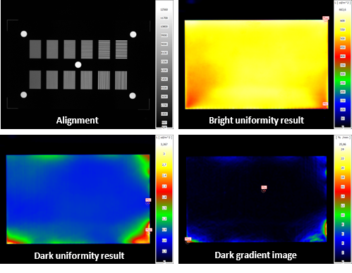
LMK BlackMURA Features at a Glance
- Full compliance with DFF BlackMURA
- Full-surface uniformity assessment of the display
- Adaptable for special cases such as DeepGrayMURA in OLEDs
- Compatible with image stitching for pillar-to-pillar and ultra-wide automotive displays
- Reproducible results thanks to standardized alignment
- Automation possible via SDK and the LMK Position robot platform
- Usable in confined spaces near production lines thanks to short-distance correction
- Perspective correction for angle-dependent analyses, e.g., for split-view displays
Simple 3-Step Procedure with Live View
The BlackMURA measurement is performed using a straightforward three-step process following an initial alignment:
- White image measurement to assess bright uniformity
- Black image measurement to detect dark non-uniformities
- Gradient analysis to evaluate local contrasts and brightness transitions
Thanks to the integrated live view mode of the LMK luminance measurement camera, camera alignment is fast and intuitive: position and angle can be checked and adjusted in real time. Flexible adaptations such as grayscale modifications (e.g., DeepgrayMURA for OLEDs) and full automation via SDK or the LMK Position platform ensure precise and reproducible results.
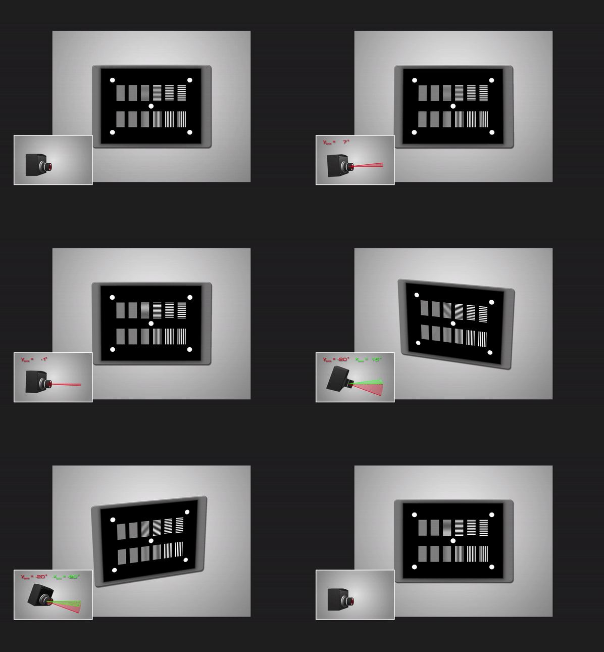
Thanks to the live view mode, alignment changes are recognized immediately.
Corrections for Compact Measurement Environments
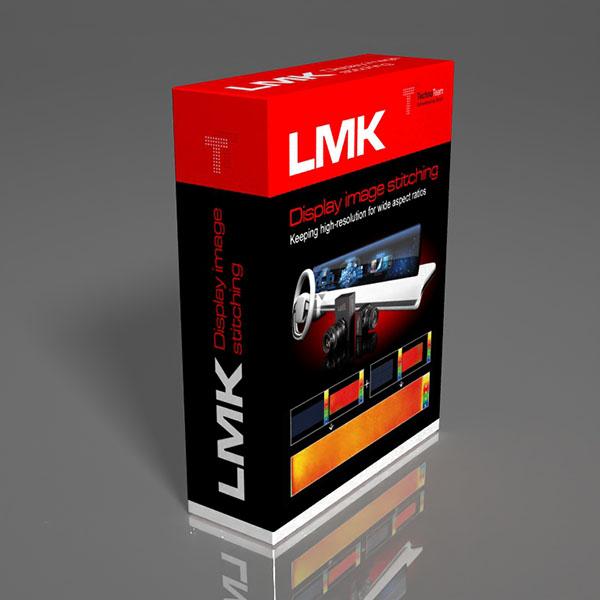
The short-distance correction developed by TechnoTeam (external link to our technical article) enables BlackMURA-like evaluations even in confined spaces – ideal for compact production lines. At the same time, it can be combined with image stitching for large-format displays (e.g., pillar-to-pillar), where multiple camera perspectives are precisely merged into one overall image through lateral movements (external link to our technical article).
FAQ — BlackMURA
What is BlackMURA — and what makes it the de-facto standard for automotive-display uniformity?
BlackMURA is a measurement and evaluation procedure for the low-frequency luminance uniformity of a display — i.e. the slow, broad luminance variations that appear as bright halos, dark corners or hazy patches across an otherwise uniform image. The procedure was developed jointly by the German Automotive OEM Working Group Displays and the German Flat Panel Forum (DFF) and is published as the Uniformity Measurement Standard for Displays (currently v1.30). It is referenced from the Display Specification for Automotive Application used by major German OEMs, which is why "BlackMURA" has become the everyday name for low-frequency uniformity testing of automotive panels.
The procedure ties two things together that are usually treated separately: a detailed alignment recipe (so that two labs using two different cameras arrive at the same number) and a defined set of metrics (bright uniformity, dark uniformity, and a dark-image gradient) that summarise the panel's visual uniformity in a few numbers.
What does "low-frequency uniformity" mean — and how is it different from sparkle, DeMURA or halo?
The four terms describe different spatial frequencies of the same underlying physical signal (luminance vs. position on the panel):
- Low-frequency uniformity → BlackMURA. Slow gradients over many pixels (centre-to-edge falloff, corner darkening, large mura blobs). Typical filter scale on the page: ~2.24 mm, derived from the maximum of the human contrast sensitivity function at a typical automotive viewing distance.
- High-frequency uniformity → Display Sparkle. Sub-millimetre luminance variation from anti-glare layers and pixel structure.
- Pixel-level uniformity → DeMURA. Subpixel-by-subpixel luminance/chromaticity correction data for OLED, MicroLED and LED panels.
- Halo (FALD / local dimming). A perception-related artefact around bright objects on a dark background in LCDs with full-array local dimming backlights.
LMK BlackMURA targets the first category and always evaluates the entire active display surface. It is the typical end-of-line (EOL) acceptance measurement on the line and the lab reference against the OEM specification. The 2.24 mm box filter deliberately suppresses higher-frequency content so that the result tracks driver perception across the full panel rather than pixel-level detail.
What exactly does the BlackMURA procedure measure, in three steps?
After an initial alignment, the procedure captures two images of the display and runs one numerical comparison:
- White-image measurement → bright uniformity, computed as the ratio of the lowest to the highest luminance across the active image area (after applying the 2.24 mm box filter and a small erosion of the active-area mask).
- Black-image measurement → dark uniformity, computed in the same way on the black image.
- Gradient image of the dark luminance → its local maximum, which catches small, sharp dark-image defects that a min/max ratio would miss.
The combination is important: bright uniformity captures large-scale brightness falloff, dark uniformity captures backlight bleed and contrast loss, and the gradient image catches sharp localised mura that would otherwise be averaged away. A panel is judged against the OEM specification on all three values.
What does "DFF-compliant alignment" actually involve — and why is alignment so critical?
The DFF standard does not just define metrics; it defines a stepwise setup procedure that must be followed before any measurement is captured. The procedure has three parts:
- Geometrical alignment — limits the angles between the camera's optical axis and the display normal to ≤ 0.5° for each of the three axes, and limits the lateral offset between the optical axis and the display centre to < one display pixel. The LMK luminance measurement camera live-view mode is used to interactively check and reach this tolerance.
- Reproducible defocus — uses a grill test pattern to set a defined optical defocus that suppresses Moiré without affecting low-frequency content. The defocus is set so that the modulation depth of the 4-pixel-wide grille pattern lands typically between 50 % and 90 %.
- Measurement-field-angle test — verifies that the chosen measurement distance is large enough so that the influence of oblique viewing directions on the measured luminance stays below 5 % at the corners of the display.
Without this discipline, two labs measuring the same panel get different numbers — driven not by the panel but by the geometry.
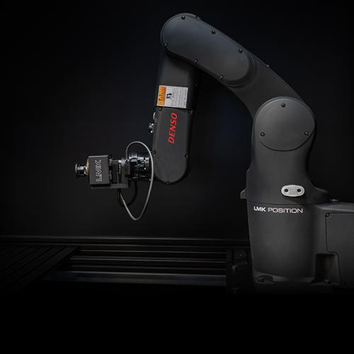
All three alignment steps can be automated on the LMK Position robotic platform — the live luminance image steers the 6-axis robot into the BlackMURA-compliant pose, and the measurement-field-angle test is run by lateral robot moves.
Why is the measurement distance not fixed by the standard — and how big does it actually get?
The BlackMURA standard fixes everything except the measurement distance, because the required distance depends on three things you cannot fix in advance: the field of view of the lens, the size of the panel, and the angular luminance variation of the panel itself. The angular variation can be modest on a typical TFT, but is pronounced on panels with privacy films or switchable privacy modes, where the design intent itself is a strong angular falloff — those panels often need significantly larger distances than the lens-and-size formula alone would suggest. The standard handles all of this with the measurement-field-angle test: the lab uses a distance at which that test stays within the 5 % limit.
For a classical 12.3″ 16:9 automotive panel with a maximum acceptable field-of-view angle of ~10°, this leads to roughly 1.5 m measurement distance. For modern pillar-to-pillar panels, the required distance scales linearly with the panel width — a 48″ 6:1 pillar-to-pillar display would need around 5.0 m measurement distance.
In production environments and small labs this becomes impractical, which is exactly the gap that short-distance correction and Image Stitching fill.
What does the ILMD (the camera itself) have to be capable of?
The standard places explicit limits on the imaging luminance measurement device — because a mismatched or non-uniform camera will pollute the result. The most important characteristics:
- Non-uniformity index f₂₁ ≤ 2 %. This is the dominant ILMD influence on BlackMURA results. The smaller the panel's own uniformity defect, the larger the proportional contribution of f₂₁. Cameras with f₂₁ > 2 % cannot be used.
- Spectral mismatch f₁′ ≤ 5 %. Quantifies how much the camera's spectral response deviates from the photopic luminous efficiency function V(λ) — relevant as the spectrum changes between dark and bright mode.
These characteristics are formalised in CIE 244:2021 and DIN 5032-10. All LMK luminance cameras used for BlackMURA workflows are characterised and certified against these indices as part of TechnoTeam's standard calibration. A geometrical calibration is not required.
How does short-distance correction work — and what are its limits?
In a compact production cell, the measurement distance is often impractical. The short-distance angular correction makes BlackMURA work at much shorter distances: the panel's angular luminance distribution is measured once, e.g. with a conoscopic lens, and used to cancel the contribution of oblique viewing directions from the short-distance image. A one-shot short-distance measurement then yields the same uniformity result as a long-distance reference (validated in our study "Distinguished Paper: Short Distance Uniformity and BlackMURA Measurements" at 350 mm vs. 1100 mm). The same approach is also the practical way to handle panels with strong intrinsic angular falloff such as privacy films or switchable privacy displays.
Limits of the approach: The correction assumes the same angular distribution across the active surface — a model assumption that local mura defects can violate. Practical recommendation: Keep the measurement distance as large as the production cell allows, so that the correction factors stay small.
Where the cell forces an even shorter distance, the residual per-tile field angle can be reduced further by combining the correction with LMK Image Stitching: each tile is captured at a smaller field of view, the angular correction is applied per tile, and the tiles are merged into a seamless full-resolution image. This pushes the workable measurement distance down to 300–400 mm even for large pillar-to-pillar panels.
What is DeepGrayMURA — and how does LMK BlackMURA handle OLED-specific cases?
OLED and MicroLED panels behave differently from LCDs in the dark: each subpixel is its own light source, so the pure-black image is genuinely "off" — there is no backlight leakage for a classical dark-uniformity measurement to characterise, and the dark image alone is therefore not the informative test case for these panels. The defect that does matter lives at low grey levels, where the per-subpixel luminance variation becomes visible as a coarse, grainy darkening — called DeepGrayMURA. It is not a standard BlackMURA defect, but the same measurement pipeline addresses it by running the procedure on a defined low grey level rather than on the pure black image. LMK BlackMURA exposes this via grey-scale modifications in the test-pattern set.
For per-pixel correction of OLED panels at the production stage, see also the dedicated LMK DeMURA add-on and the DeMURA application page.
How does LMK BlackMURA integrate with LMK Position for automation?
The BlackMURA setup procedure — geometric alignment to ≤ 0.5°, lateral alignment to < 1 display pixel, reproducible defocus, and the measurement-field-angle test — is exactly the kind of operator-dependent step that benefits most from automation. On a 6-axis LMK Position platform:
- The robot drives the camera to a stored pose, then the live luminance image steers the final fine alignment to BlackMURA tolerances in seconds.
- The measurement-field-angle test is run automatically by lateral robot moves and the 5 % verification is logged with the measurement.
- For short-distance stitched measurements, the robot drives the tile pattern reproducibly across the panel and TechnoTeam's Advanced Pixel Registration (APR) workflow fuses the result without re-fixturing.
This is the practical bridge between BlackMURA as a standard and BlackMURA as a metric: alignment quality is no longer an operator skill, and the same camera, lens and DUT yield the same number across shifts and labs.
Is the LMK BlackMURA LabSoft add-on suitable for inline production — or only for the lab?
The LMK BlackMURA LabSoft add-on is primarily designed for laboratory use: development, qualification, prototype evaluation, OEM specification compliance and root-cause analysis. The LabSoft workflow gives the engineer full visibility of the measurement (luminance images, masks, gradient maps, intermediate values) — useful in the lab, but more functionality than a line operator needs.
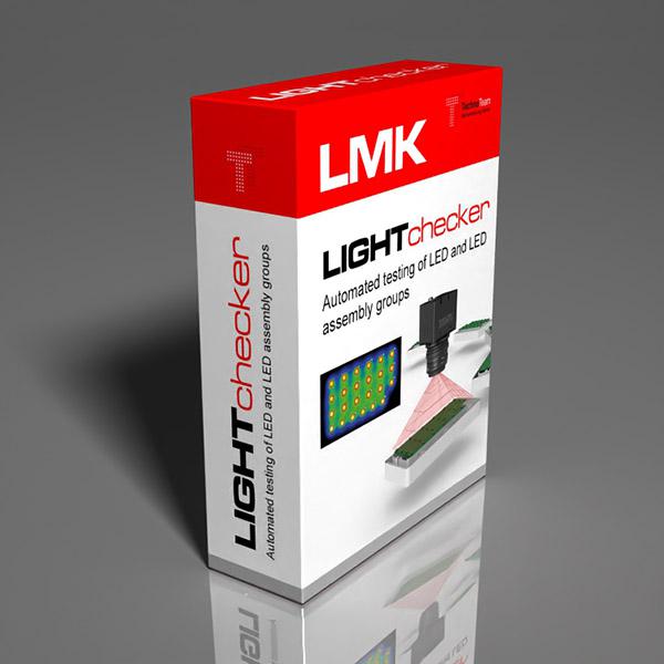
For inline / end-of-line production use, the same BlackMURA evaluation is integrated into TechnoTeam's LightChecker — a system tailored to fixed-tact-time line measurement with a streamlined operator interface. The algorithmic core is the same, so a panel that passes BlackMURA in the lab passes the same evaluation in the line.
In short: LabSoft for the lab, LightChecker for the line — same standard, same numbers.
RELEVANT PRODUCTS AND APPLICATIONS
Downloads
Publications
Distinguished Paper: Short Distance Uniformity and BlackMURA Measurements
Journal of the Society for Information Display
The increasing display sizes and changing form factors of displays, including automotive displays, lead to impractical measurement distances for lateral uniformity measurements. This contribution suggests and exemplarily applies two alternative and combinable methods to allow lateral uniformity measurements at low distances and describes an adjusted BlackMURA compliant validation procedure. The proposed methods are validated with a high-quality display device and are compared to results using the standard long-distance measurement procedure.
Repeatability and Reproducibility Considerations for BlackMURA Measurements
Proceedings of the International Display Workshops Volume 26 (IDW '19)
The “Uniformity measurement standard for Displays”, which is used for automotive applications, describes precise setup and alignment procedures to ensure reproducible measurement results. However, the influences of the tested device and the ILMD are not considered in detail. This contribution shows experiments and simulations to estimate these influences as well.
Conformity assessment with examples for BlackMURA measurements
Society for Information Display
To decide whether a display works according to the specification it is not only necessary to take the measurement values into account. The measurement uncertainty also plays a significant role in this decision. Besides some basic knowledge about the measurement uncertainty evaluation, the paper shows the main contributions and their influences for the key values of the BlackMURA standard. Using the rules of conformity assessment, the use of tolerance intervals and acceptance intervals is explained in detail to give all parties (OEMs, manufacturer of display and measurement system manufacturer) the chance to discuss their quality metrics in a reasonable manner.
Invited Paper: Recent Standardization Efforts and Measurement Procedures of German Automotive OEM and German Flat Panel Forum (DFF)
SID International Symposium 2016
The requirements of automotive displays differ to a large extent from consumer and industrial displays. In order to reduce the effort in specifying and evaluating high quality displays, German automotive OEMs, Tier 1/2 and the German Flat Panel Forum have launched a cooperation.
- Type:
- Add-On
- Applications:
- Automotive Display
- Measurands:
- Light measurement
- Tasks:
- Development & Industry